Clearer sections and safer complex edits
Inspect your models with color-matched sections and smoother cut edges, finish complex geometry with more predictable selections, and explore visual release guides with practical instructions.
See inside. Keep your colors.
Cut faces keep the color and material of each part. Subtle hatching marks the material exposed by the section.
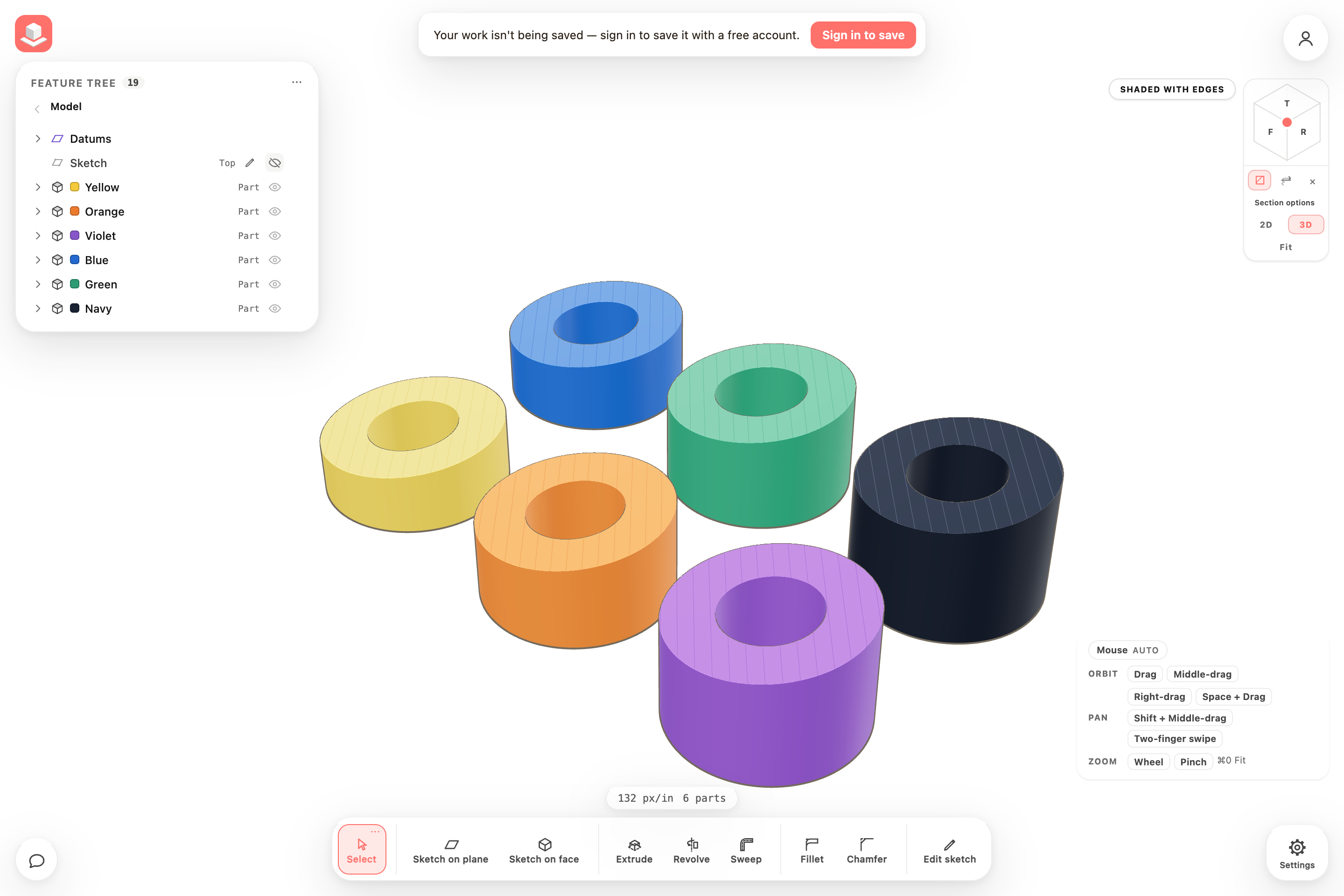
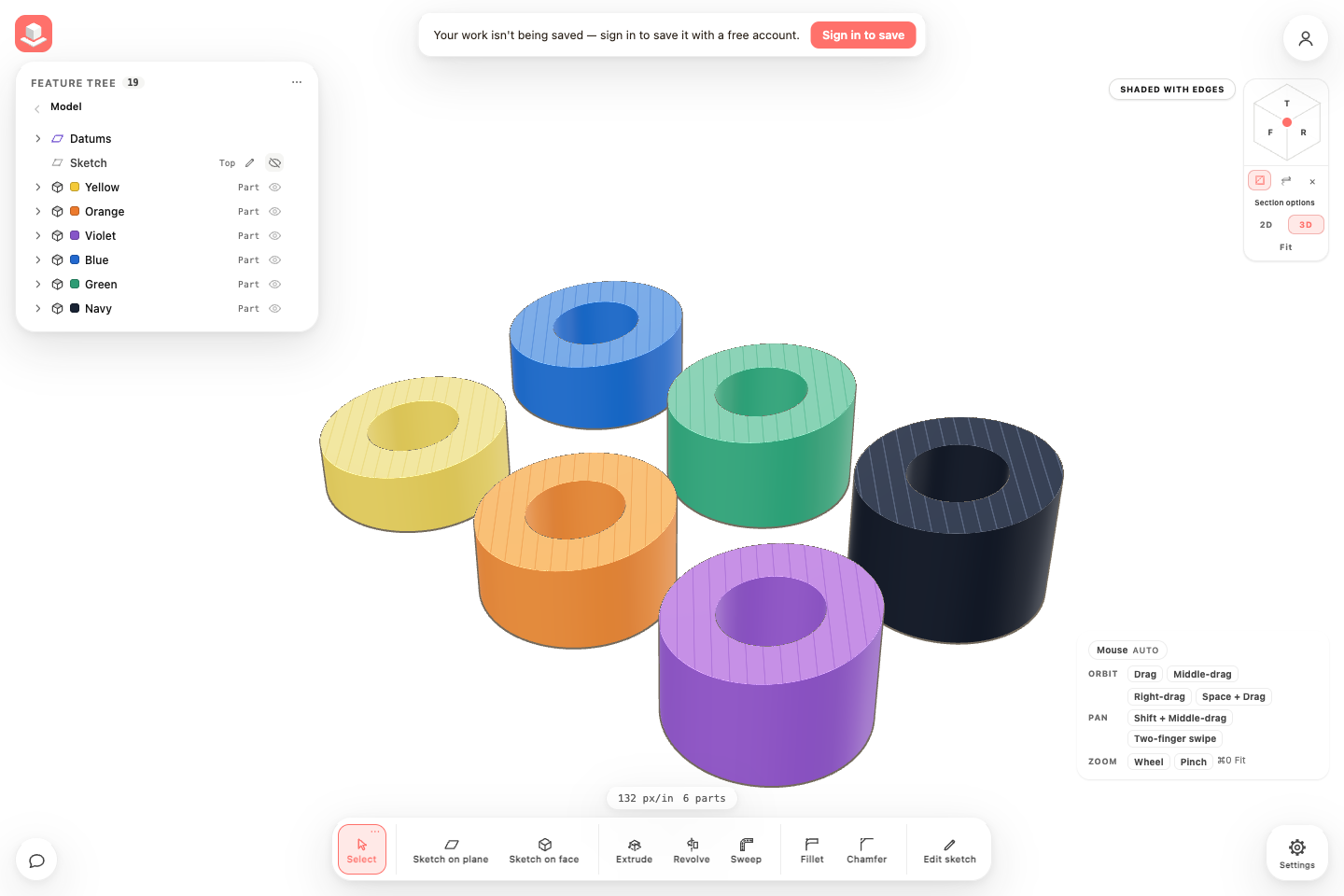
Inspect the cut from every angle
Orbit around a sectioned assembly to see the bores and cut material. Turn Presentation off when you want to adjust the section again.
Choose one edge or a smooth chain
Fillet and Chamfer now offer a choice between one whole logical edge and a smooth connected chain. A circular rim or spline counts as one edge, even when the display mesh contains many segments.
Finishes are limited by the surrounding material and document precision. Some tightly intersecting or collapsed finishes still need a smaller size or a revised selection. If an earlier edit removes or splits a selected edge, reselect it instead of applying the finish to a different rim.
- Open the spline port carrier demo and select Fillet or Chamfer.
- Choose Single edge for one rim, or Smooth chain for connected edges. Hover to check the highlighted selection before clicking.
- Enter the radius or distance and inspect the preview. If the size is adjusted, check the applied dimension before choosing Confirm.
Find the details behind an update
What’s New now begins with a short overview of each release. Choose Read update to open its permanent page, where you can find instructions, visual examples and the full list of changes.
Copy the page’s URL to share a specific release. Older releases remain available from the feed and the neighboring-release links.
Inspect a part with a section view
A section view reveals the material and openings inside a model. Cut faces keep each part’s color and finish; diagonal hatching distinguishes cut material from an ordinary surface.
This release adds display improvements to interactive sections. Saved-view locking and persistent named views are still in development.
- Open a model in 3D and click Cross-section beside the view cube.
- Click a surface to place the section, then drag its handle to inspect different depths. Use Flip the section to the other side to change which half remains.
- Open Section options and toggle Show hatching. This preference is remembered in this browser.
- For a clean view, open the rendering mode menu and enable Presentation. Section fills stay visible while sketches, grids, editing planes and handles are hidden. Turn Presentation off to adjust the section again.
Everything in this release
Added
- What’s New now has a concise update feed and individual release pages with instructions, screenshots, videos, and direct links to examples.
- What’s New can show spotlight images, interactive before-and-after comparisons, and playable videos with captions alongside release notes.
Improved
- What’s New brings each release’s features and fixes together in grouped notes, with an optional introduction and selected visual highlights.
- Section cuts use multisample antialiasing on opaque parts, smoothing the cut boundary without an extra rendering pass.
- Presentation mode hides the section editing plane and orange outlines while keeping the colored, hatched cut faces visible.
- Section fills use the part’s lighting and material finish, so dark colors no longer look much darker where the model is cut.
- Default-colored parts use their stored material finish consistently, including while moving or previewing a part.
- Cut faces now stay visible and update their colors when the model finishes rebuilding.
- Section views show subtle diagonal hatching tinted to each part, including dark colors, and keep holes clear; Section options lets you turn hatching off and remembers your preference in this browser.
Fixed
- Tiny rounds that collapse at document precision now refuse the affected edge with clear feedback instead of returning invalid corner geometry.
- Saved fillets and chamfers ask for a new edge selection when upstream edits remove, split, or merge a separately selected curved edge, instead of finishing a different rim or the opposite spline tip.
- Chamfers around existing rounds on convex parts retain their requested setback as display detail increases.
- Tiny chamfers that cannot form a distinct bevel at document precision now explain the limit and preserve the original solid.
- Very small fillets on sharp spline tips remain valid when display detail increases, instead of being mistaken for a pinched face when adjacent curve samples snap to the same point.
- Fillet and chamfer cards let you choose one whole edge or a smooth connected chain, with hover previews matching the choice; a selected face can still finish its whole perimeter
- Picking an intersection between curved surfaces now distinguishes separate meeting points, so finishing a sharp two-spline tip no longer also changes the rear of the part
- Newly selected curves on fillets and chamfers keep their whole connected edge when display resolution changes, instead of referring to individual display segments
- Adding a boss or extending a face no longer draws a join across a continuous bore or flat surface when Show tangent edges is enabled; real shoulders, extremely shallow bends and fillet boundaries remain visible
- Repeated cuts through joined curved walls no longer leave short feature seam fragments around the new openings
- Extending a curved boss after it meets an uneven surface no longer leaves seam fragments around the extension or later angled drilling; real intersection edges stay visible
- Editing or dragging one design in a sketch keeps unrelated designs exactly in place, including after connecting and separating constrained shapes
- Dimensions and constrained dragging stay stable when very short horizontal or vertical edges connect to geometry far along their extensions
- Spline constraints use the selected position along the curve and respond correctly when control handles move
- Large dimension changes can follow smaller valid steps automatically; rejected edits preserve the entire sketch, reference measurements, and undo/redo history
- Partially overlapping straight sketch lines form selectable, extrudable profiles while keeping their source references
- Straight extrusion walls remain available for Sketch on face when overlapping sketch lines subdivide their boundary
- Failed sketch solves report that they could not settle instead of claiming there is no possible solution, and scripted edits report failures accurately
- Added regression checks for repeated edits, undo, recovery and reopening across the kettle, spline carrier, flow housing, bracket and enclosure, including retained fillets, chamfers and later cuts
